STUDY OF 4 BIT COUNTERS (SYNCHRONOUS & ASYNCHRONOUS) – GUPTA BRAND 200386

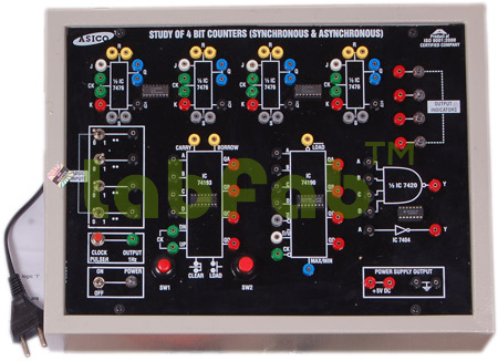
Objective : To Study and verify the truth tabels of two Bit, four Bit up, down and Modulo Asynchronous (Ripple) counters using IC 7476, Ring & Johnson Counter using IC 7476, four Bit Up Down and Programmable Synchronous counter using IC 74193, Decade Up-Down Counter using IC 74190.
Features : Instrument comprises of DC Regulated Power Supply 5VDC/150mA, 1Hz monoshot clock pulse, Two output indicators, symbolic diagram for 4 ‘JK ‘ flip-flops Printed & connections for inputs & outputs brought out at sockets on the front panel

Download PDF

STUDY OF ADDERS & SUBTRACTOR USING OR, EX-OR, AND & NOT GATES – GUPTA BRAND 200379

Objective : To verify the truth table of Digital Half Adder, Half Subtractor, Full Adder & Full Subtractor using OR, AND, EX-OR & NOT gates.
Features : Instrument comprises of DC Regulated Power Supply 5V/150mA for logic inputs, 4 SPDT switches provided for selecting logic ‘1’ & logic ‘0’, 2 Red LED output indicators, circuit diagram printed for 1 two input ‘OR’ gate, 2 two input ‘AND’ gates, 2 ’NOT’ gates & 2 EX-OR gates & their respective IC’s placed inside the cabinet & connections brought out at sockets.

Download PDF

STUDY OF ENCODER & DECODER CIRCUITS – GUPTA BRAND 200385

Objective : To Study and verify the truth tables of Binary to gray code convertor, BCD to seven segment Decoder, BCD to decimal Decoder, Decimal to BCD Encoder.
Features : Instrument comprises of DC Regulated Power Supply 5VDC/150mA, 4 SPDT switches provided for selecting logic ‘1’ & logic ‘0’,1Hz monoshot clock pulse, 4 output indicators, Circuit diagram for IC 7490, IC7447 & 7-segment display printed & connections for various inputs & outputs brought out at the sockets on the front panel.

Download PDF

STUDY OF LEFT, RIGHT & PROGRAMMABLE SHIFT REGISTER – GUPTA BRAND 200384

Objective : To study & verify truth table of Left, Right & Programmable Shift Register using IC 7495.
Features : Instrument comprises of DC Regulated Power Supply 5VDC/150mA, 4 SPDT switches provided for selecting logic ‘1’ & logic ‘0’, 1Hz monoshot clock pulse, four output indicators, Circuit diagram for IC 7495 printed and two switches for serial input & Mode control.

Download PDF